by Kara Peterman and Nabil Rahman
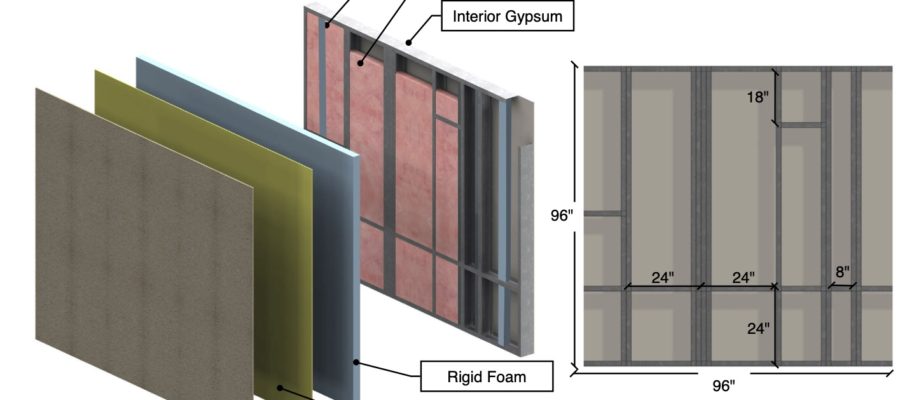
Understanding and designing for thermal performance in buildings is necessary for occupant comfort and energy efficiency. This is especially true for steel structural systems, because of the relatively high thermal conductivity of carbon steel. Finite element modeling can be high-throughput for heat transfer problems; models can be constructed and executed with little computational time and expense.
This post is intended to be the “first resource” for someone interested in taking a deeper dive into heat transfer in buildings. It is by no means exhaustive, and exists to point the reader in the correct direction.
Fundamentals:
- Climate zone (and thus insulation thickness) is critical – results are not transferrable between climate zones. Generally speaking, any attempt to break the thermal bridge must span the insulation layer, though this is dependent on structural system and thermal break strategy.
- Heat transfer problems in building structures must be modeled in three-dimensions
- Connecting elements, like bolts and fasteners, must be modeled, with accurate engagement.
- Air layers must be modeled (with accurate R values – sometimes this results in modeling the air layer in two dimensions to determine its R value) and cannot be neglected as air is a thermal insulator.
- Thermal performance of the building envelope is greatly affected by thermal bridging. Thermal bridges are localized areas of high heat flow through walls, roofs and other insulated building envelope components and interfaces. Thermal bridging is caused by highly conductive elements (such as CFS) that penetrate the thermal insulation and/or misaligned planes of thermal insulation. These paths allow heat flow to bypass the insulating layer, and reduce the effectiveness of the insulation.
- Thermal bridging is often classified as discrete or continuous – discrete thermal bridges contact the structural system at points in the building envelope, whereas continuous thermal bridges bear continuously on the structural system. Cantilevers are examples of the former, shelf angles of the latter. Transmittance values are calculated as point and linear transmittance values for discrete and continuous bridging, respectively.
The thermal efficiency of an assembly can be defined as the net thermal resistance of the assembly with consideration of thermal bridging (Ro) divided by the combined thermal resistances of all the materials of the assembly in a clear filed assembly (R1D)
Resources: The following resources, reports, and guidelines are recommended reading and provide details pertinent to creating and executing a successful thermal modeling program:
| Resource | Contribution |
| ASHRAE 90.1 | Provides R values, insulation requirement, climate zones, etc |
| AISI Morrison Hershfield Report | Recent research report |
| ASHRAE Research Project 785 | Provides tested K values for CFS |
| IECC 2003 | Provides hand calculation method for simple assemblies |
| Charles Pankow Research Report – Thermal Break Strategies for Building Structures | Details an extensive thermal modeling program, coupled with potential mitigation strategies supported with experimental and computational structural analysis. |
| BC Hydro – “Building Envelope Thermal Bridging Guide 2016 | Provides many wall and roof details and assemblies with thermal performance through simulations. |
| Thermal Analysis of Cold-Formed Steel Wall Assemblies, AISI RP18-1 | Background to AISI’s simplified thermal modeling methodology. |
Software: ABAQUS, ANSYS, SolidWorks, TMG Thermal Solver, Siemens NX, Heat3 – all produce similar results, though there are pros and cons to each. The major FEM packages are particularly well adapted to complex and curved geometries. Heat3, which only does heat transfer problems, is popular in some US design firms for speed in solving 3D heat transfer problems. The AISI Morrison Hershfield report employed Siemens NX and Heat3. Therm is a free option, though is limited to two dimensional problems.

